Printed circuit board traces that carry more than 03 A should be wider. Metal-core boards follow a different process than typical PCB stackups involving glass-weave laminates thus they tend to carry different DFM rules.

Pcb Design Steps Complete Guide Cirexx
Try to determine the standard track width that will be applied within the whole design.

. You want to design Metal Core PCB you should know T-Guard for performance by Best PCB they have excellent design guide for MCPCB from single layer to double layers through Multi-layers MCPCB. Turnkey Pro Provides Fast Efficient Pricing With No Hidden Costs. Besides take into account that tracks that carry current have to be.
The IPC-2221 also explores the thermal design and ways heat dissipates from the PCBs. Follow the guidelines to layout differential pairs the ground plane and high-speed signals. Solder Mask Circuit Layer Copper layer 1oz.
MCPCBs have many advantages over other PCB types. Ad One stop service on bare board PCB solder stencil PCB assembly Turnkey PCB assembly. This specification covers qualification and performance of rigid printed boards including single-sided double-sided with or without plated-through holes multilayer with or without blindburied vias and metal core boards.
Ground signals should be soldered directly to the ground plane. Choose a metal box to shield the printed circuit board. High quality low price PCB and PCB assembly under the same roof from the same manufacturer.
Also in metal core PCB design there are many guidelines that you should follow in component selection placement and multilayer routing. We are Professional Manufacturer of Metal Core Pcb Design Guidelines company Factory Exporters specialize in Metal Core Pcb Design Guidelines wiht High-Quality. June 4 2021.
Metal Core Pcb Design Guidelines In Altium. PCB Materials and Stackup Design Guidelines. Find Metal Core Pcb Design Guidelines Manufacturers Suppliers from China.
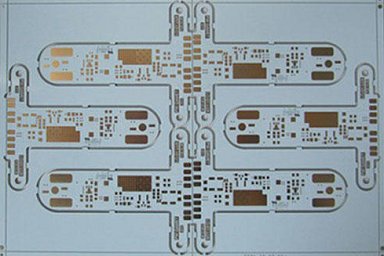
Metal Core PCBs MCPCBs are designed with a metal core base which comprises one of three metals copper aluminum or steel alloy. Designing a multilayer steel core PCB is usually a troublesome process when you dont have entry to. Design concerns and placement For best signal integrity CPUMCUSoC should be soldered directly on the PCB.
Zachariah Peterson Created. The basic design of an MCPCB consists of a copper core a thermal insulating layer IC components and a solder mask. For single-layer boards without layer transition to the metal plate standard process can do the required job with FR4 dielectrics where the layers are pressed and attached to the metal plate.
What can I do for you. Metal Core PCB Design Guidelines. Metal core PCBs are made using copper iron or aluminum in their base.
Ad Trusted leader in Flex Circuits Rigid-Flex PCB Design Fabrication Assembly. To 2oz Dielectric Layer Metal Core Layer Heat Sink Types of Metal Bases used in MCPCBs Aluminum substrate The aluminum printed circuit boards offer good heat dissipation and heat transferring ability. Your printed circuit board design will likely require different nets that will carry a wide range of currents which will dictate the required net width.
IPC 6012 class 2 Quality and performance. You can also download it here. Design Your Metal Core PCB in Altium Designer.
T-guide for Performance T-guide for Manufacturability Single Layer IMpcb Fabrication Guideline. Any sockets in between might reduce the signal quality. Document Revision History for the Intel Agilex Device Family High-Speed Serial Interface Signal Integrity Design Guidelines.
Their external layers however are made similarly with those of FR4 PCBs. Using Metal Core Printed Circuit Board MCPCB as a Solution for Thermal Management FA where A constant Ffailurerate E activation energy in electron volts eV K Boltzmanns constant 863 x 10 eVK T junction temperature in Kelvin If a device with activation energy E 065eV were operating at 50 C and its temperature raised to 60 C. It makes the copper PCB even more powerful in real applications.
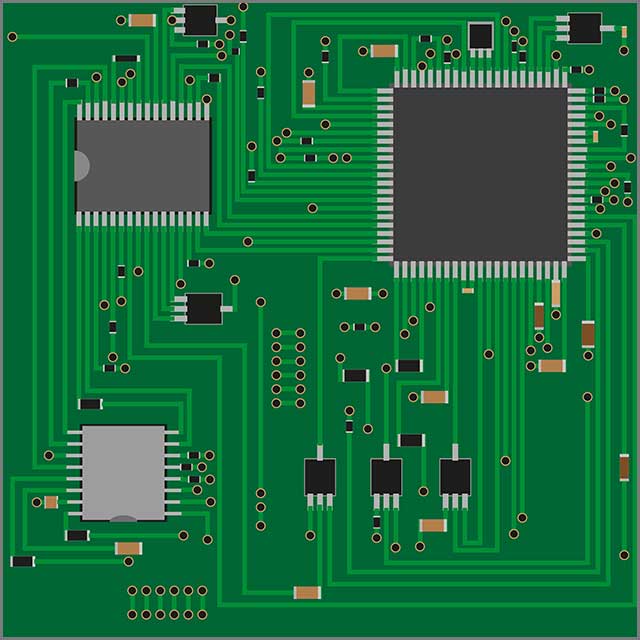
Mitigating Insertion Loss with Dielectric Material 132. Metal core PCBsare the result of a systematic procedure that takes great care of the metallic layers in the stackup. Place debugtrace connector as close as possible to the CPUMCUSoC to minimize routing length.
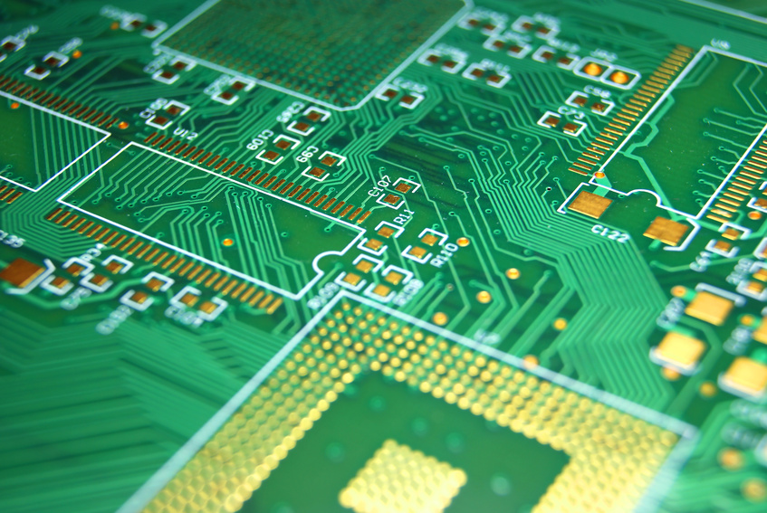
Ad Start By Uploading Your BOM Get An Instant Quote For Fabrication Assembly Components. The image below shows the typical. This design is also a COB MCPCB or Chip-On-Board PCB.
Its recommended to provide a 0010 width for low current analog and digital signals. Considering the width of tracks on PCB is another critical thing that should be done at the early stages. Provide controlled impedance on all clock lines and.
The mechanical structure is made with insulating materials laminated between layers of conductive material. The basic structure of MCPCB comprises of the following. These three metals are chosen for particular reasons.
Aluminum is capable of transferring and dissipating high levels of heat easily. PCB Design Guidelines 15. Also this standard considers how conductor clearance and PDN bus layouts should be on the PCB.
PCB design and manufacturing are indivisible sides. Use a ferrite core on the DC power cord to reduce EMI. Most commonly used 1oz.
It addresses final finish and surface plating coating requirements conductors holesvias frequency of acceptance testing and quality conformance as well as. Just like any other PCB you need to follow some basic DFM guidelines for your particular board if you want to ensure a successful fabrication run. The MCPCB or metal core PCBs are manufactured around epoxy resin due to its adhesive capacity.
Design Fabrication Assembly of Flex Rigid-Flex Printed Circuit Boards. On each side the PCB has copper substrate or foil and the middle is sandwiched of a copper circuit board for high thermal and electric conductivity. It shouldnt be too narrow or thick since it may lead to short.
Copper is more expensive than aluminum unlike aluminum PCB making it an economical option for some applications. DFM for Metal-Core PCBs. The IPC-2221 is a general standard that envelops every aspect of the PCB design.

How To Choose Pcb Board Pcb Board Electronic Components Boards

The Basics Of Metal Core Pcb Design And Manufacturing Nwes Blog
Make Sure To Consider These Factors When Creating A Pcb Layout Blog Pcb Unlimited

What Is A Metal Core Pcb Mcpcb Diy Electronics Pcb Design Electronics Projects
The Basics Of Metal Core Pcb Design And Manufacturing Nwes Blog
Tips And Tricks For An Efficient Pcb Layout Blog Pcb Unlimited

Your Guide To Flexible Pcb Design Layout
Pcb Layout 6 Important Things To Consider When Designing Your Pcb
0 comments
Post a Comment